

Samsung Dishwasher Error Codes Explained!
Samsung dishwashers show error codes when something stops the cycle from running correctly. These codes usually point to issues with water supply, draining, heating, sensors, or internal communication.
Before You Begin: Safety First!
Always prioritize your safety when dealing with any appliance repair. Before attempting any troubleshooting or repair, unplug your Samsung dishwasher from the power outlet or turn off the circuit breaker.
Understanding Common Samsung Dishwasher Error Codes:
Here’s a breakdown of some frequently encountered error codes and potential solutions:
dC3: Auto Door Open Error
This error indicates an issue with the automatic door opening mechanism, a feature on some Samsung models designed to aid drying.
- Possible Causes:
- Problem with the auto-release mechanism itself (e.g., wax motor).
- Faulty wiring harness connecting the mechanism to the main control board.
- Issue with the main PCB (Printed Circuit Board).
- The auto-release function is disabled in the settings.
- Troubleshooting Steps:
- Check Auto-Release Setting: Ensure the auto-release function is enabled. This can usually be done through a specific button combination on the control panel (refer to your user manual for the exact steps, but it often involves holding ‘Delay Start’ and ‘Sanitize’ simultaneously, then using ‘Sanitize’ to toggle the setting).
- Inspect Harness and Connections: With the power off, visually inspect the wiring harness running from the auto-release mechanism to the main PCB for any visible damage or loose connections.
- Advanced Checks (Requires Technical Knowledge): For those comfortable with electrical testing, you can check the resistance of the wax motor and verify continuity of the harness wires. You can also check for the correct voltage supply to the mechanism from the main PCB when the function should be active (approximately 120 VAC). If these checks fail, the wax motor, harness, or main PCB may need replacement.
AE6, AC6: BLDC Motor Communication Error
These codes signal a communication problem between the main control board and the Brushless DC (BLDC) motor or its inverter.
- Possible Causes:
- Poor connection between the main PCB and the inverter PCB.
- Faulty inverter PCB.
- Faulty main PCB.
- Troubleshooting Steps:
- Check Connections: Ensure the connectors between the main PCB and the inverter PCB are securely seated.
- Consider Component Replacement: If secure connections don’t resolve the error, the inverter PCB is often the first component to suspect. If replacing the inverter PCB doesn’t fix the issue, the main PCB may be the culprit.
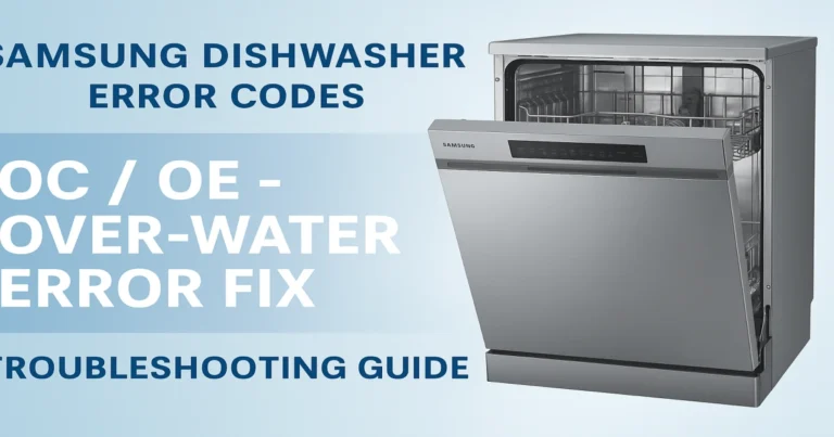
OC, OE: Over-Water Error
This indicates that the dishwasher has detected an excessive amount of water in the tub.
- Possible Causes:
- Kinked or clogged drain hose.
- Clogged drain filter or sump.
- Issues with the drain pump.
- Defective water inlet valve that is stuck open.
- Overfill sensor malfunction.
- Troubleshooting Steps:
- Inspect Drain Hose: Check the drain hose for any kinks, twists, or blockages from the dishwasher to the drain connection (under the sink or to a garbage disposal). Ensure the drain hose is properly installed with a high loop to prevent backflow.
- Check Sink Drain/Disposal: If connected to a garbage disposal, ensure the knockout plug has been removed. Run the sink to check for drainage issues in your home’s plumbing.
- Clean Filters and Sump: Remove and thoroughly clean the dishwasher’s drain filter and sump area, as these can become clogged with food debris.
- Inspect Drain Pump: With the power off and water removed, inspect the drain pump impeller for any foreign objects.
- Check Water Inlet Valve: If water enters the dishwasher even when the power is off, the water inlet valve is likely faulty and needs replacement.
- Advanced Checks: You can test the drain pump’s resistance and check for voltage supply to the pump from the main PCB in drain test mode. Inspect the case break for blockages.
FC: Fan Motor Error
This error relates to a problem with the dishwasher’s fan motor, often part of the drying system.
- Possible Causes:
- Faulty BLDC fan motor.
- Damaged wire harness or connections to the fan motor.
- Defective main PCB.
- Troubleshooting Steps:
- Access Service Mode: Some models allow you to test the fan motor in a service or Smart Install mode (refer to your manual).
- Check Connections and Harness: With the power off, inspect the wiring harness and connectors for the fan motor for any damage or loose connections.
- Advanced Checks: You can measure the voltage supplied to the fan motor from the main PCB and check the continuity of the harness wires. If these tests indicate a problem, the fan motor or harness.
3E, 3C: Circulation BLDC Motor Error
These codes typically indicate an issue with the main circulation BLDC motor, which pumps water to the spray arms.
- Possible Causes:
- Faulty BLDC motor.
- Clogged microfilter.
- Excessive suds in the tub.
- Faulty high-pressure switch.
- Troubleshooting Steps:
- Check and Clean Filter: Ensure the microfilter is clean and free of debris.
- Address Suds: Excessive suds can interfere with the motor’s operation. Run a cycle without detergent or with a dishwasher cleaner designed to reduce suds.
- Check Motor Connections: With the power off, inspect the connections to the BLDC motor.
9C1, 9E1: Supply Voltage Error
These errors indicate a problem with the electrical power being supplied to the dishwasher.
- Possible Causes:
- Supply voltage is too low (below 110 VAC).
- Damaged power cord.
- Issue with the dishwasher’s internal filter or main PCB related to power regulation.
- Troubleshooting Steps:
- Check Power Outlet: Ensure the dishwasher is plugged into a functioning outlet providing the correct voltage (ideally 110-120 VAC). You can test the outlet with a multimeter.
- Inspect Power Cord: Check the power cord for any visible damage.
- Advanced Checks (Requires Technical Knowledge): If comfortable, you can measure the voltage coming into and out of the dishwasher’s internal filter. If the output is abnormal while the input is correct, the filter may be faulty.
bC2, bE2: Key Input Error / bC3, bE3: Button Input Error
These codes suggest a problem with the control panel buttons or their communication with the main control board.
- Possible Causes:
- Moisture on the control panel.
- A button is stuck or continuously pressed.
- Faulty control panel/display module.
- Problem with the wiring harness connecting the control panel to the main PCB.
- Troubleshooting Steps:
- Clean and Dry Control Panel: Wipe down the control panel to ensure there is no moisture interfering with the buttons.
- Check for Stuck Buttons: Gently press each button on the control panel to ensure none are stuck.
- Check Connections: With the power off, inspect the connections for the control panel assembly at the sub-PCB and the harness to the main PCB.
- Component Replacement: If a specific button is stuck (indicated by bC-2), the control panel may need replacement.
LC, LE: Water Leakage Error
These codes are triggered when the dishwasher’s leak sensor detects water in the base of the unit.
- Possible Causes:
- Loose or damaged water supply hose connection.
- Leaking water valve.
- Improperly leveled dishwasher causing water to overflow.
- Problem with the drain pump assembly or sump seal.
- Blocked drain line causing overflow.
- Damaged tub or tub seal packing.
- Using improper detergent (e.g., hand dish soap) causing excessive suds.
- Unassembled or damaged spray arms (vane).
- Troubleshooting Steps:
- Inspect for Visible Leaks: Carefully look for any visible water leaks around the dishwasher, paying attention to the water supply and drain hose connections. Tighten connections if necessary.
- Check Dishwasher Level: Ensure the dishwasher is properly leveled according to the installation instructions.
- Verify Drain Line: Check for any blockages in the drain line that could cause water to back up and overflow.
- Inspect Internal Components: With the power off and water removed, check the drain pump assembly, sump, and tub seal packing for any damage or improper assembly.
- Use Proper Detergent: Only use detergent specifically designed for automatic dishwashers. Hand dish soap will create excessive suds and can cause leaks.
- Check Spray Arms: Ensure the spray arms are properly assembled and not damaged.
- Advanced Checks: If you suspect the water valve, it may need to be inspected or replaced.
HC1, HE1: Heater Error / HC, HE: Heater Overheating Error
These codes relate to issues with the dishwasher’s heating element or its temperature sensor (thermistor). HC1/HE1 often indicates a general heater fault, while HC/HE specifically points to overheating.
- Possible Causes (HC1, HE1):
- Faulty heating element.
- Faulty wiring harness to the heater.
- Issues with the main PCB’s heater relay or control circuit.
- Possible Causes (HC, HE):
- Faulty thermistor (temperature sensor).
- Main PCB not properly controlling the heater.
- Freezing temperatures affecting the sensor in cold environments.
- Troubleshooting Steps:
- Check Connections: With the power off, inspect the connections at the heating element and the main PCB.
- Advanced Checks (Requires Technical Knowledge): You can measure the resistance of the heating element. In service mode, you may be able to activate the heater and check for voltage supply. For overheating errors, the thermistor’s operation and resistance can be checked. You should also verify that voltage is not being supplied to the heater relay when the heater is not supposed to be active. If the thermistor is faulty, it needs replacement.
PC, PE: Half-Load Error
These codes indicate a problem with the dishwasher’s half-load function, which often utilizes a distributor motor to direct water to specific spray arms.
- Possible Causes:
- Faulty distributor motor or its microswitch.
- Problem with the wiring harness to the distributor motor or microswitch.
- Issues with the cam assembly that the distributor motor operates.
- Troubleshooting Steps:
- Check Connections: With the power off, inspect the connections for the distributor motor and microswitch.
- Advanced Checks (Requires Technical Knowledge): You can check the resistance of the distributor motor coil. The operation of the microswitch can be tested for proper opening and closing. The position of the cam assembly should also be checked and adjusted if necessary. The operating voltage of the distributor motor and the function of its relay on the main PCB can also be tested. Failure in these tests may indicate a need to replace the microswitch or distributor motor.
4C and 4E: Water Supply Error
These are common codes indicating that the dishwasher is not receiving adequate water.
- Possible Causes:
- Water supply valve is turned off or the water supply is interrupted.
- Kinked or clogged water supply hose.
- Clogged filter screen at the water inlet valve.
- Faulty water inlet valve.
- Troubleshooting Steps:
- Check Water Supply: Ensure the hot water supply valve to the dishwasher is fully open and that there are no issues with your home’s water pressure.
- Inspect Water Supply Hose: Check the water supply hose for any kinks or twists.
- Clean Inlet Filter: Turn off the water supply, disconnect the water hose from the dishwasher, and inspect the small filter screen at the water inlet valve for clogs. Clean if necessary.
- Advanced Checks (Requires Technical Knowledge): You can check the resistance of the water inlet valve solenoid. You can also verify that the main PCB is supplying the correct AC voltage (110-120 VAC) to the water valve when it should be filling. If the valve has proper voltage but doesn’t open, the valve is faulty.
5C, 5E: Drain Pump Error
These codes signify a problem with the dishwasher’s ability to drain water.
- Possible Causes:
- Clogged drain hose or air gap (if applicable).
- Clogged drain filter or sump.
- Foreign object in the drain pump.
- Faulty drain pump.
- Troubleshooting Steps:
- Check Drain Hose and Connection: Inspect the drain hose for kinks or blockages. Ensure the connection to the sink drain or garbage disposal is clear.
- Clean Filter and Sump: Clean the drain filter and sump area thoroughly.
- Inspect Drain Pump: With the power off and water removed, check the drain pump impeller for any foreign objects that might be obstructing it.
- Advanced Checks (Requires Technical Knowledge): You can measure the resistance of the drain pump. In drain test mode, you can check for the correct voltage supply (120 VAC) from the main PCB to the drain pump.
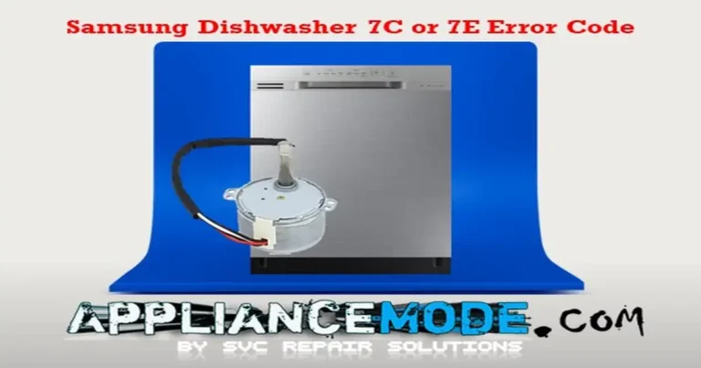
7C, 7E: Motor Vane Error
These codes are specific to models with a waterwall spray system and indicate an issue with the motor that moves the spray vane.
- Possible Causes:
- Motor gear or sensor vane is out of order.
- Something is blocking the movement of the vane.
- Problem with the wiring harness or connections.
- Troubleshooting Steps:
- Check for Obstructions: Ensure nothing inside the dishwasher is blocking the movement of the Waterwall vane.
- Check Connections: With the power off, inspect the connections for the motor vane and sensor vane.
- Advanced Checks (Requires Technical Knowledge): You can check the conductivity and resistance of the motor vane coil. The sensor vane’s operation can be checked in a service test mode (like n5).
tC, tE: Thermistor Error
These codes indicate a problem with the dishwasher’s temperature sensor (thermistor), which monitors the water temperature.
- Possible Causes:
- Faulty thermistor.
- Faulty or incorrect connections of the thermistor.
- Freezing temperatures in the installation location.
- Troubleshooting Steps:
- Check Connections: With the power off, inspect the connections for the thermistor.
- Advanced Checks (Requires Technical Knowledge): You can measure the voltage across the thermistor and its resistance (which changes with temperature). A faulty thermistor will provide abnormal readings.
AC, AE: Communication Error between Main PBA and Sub-PBA
These codes indicate a failure in communication between the main control board and the sub-control board (often associated with the display and control panel).
- Possible Causes:
- Loose or damaged connectors between the main PCB and sub-PCB.
- Faulty wiring harness connecting the two boards.
- Troubleshooting Steps:
- Reseat Connections: With the power off, carefully reseat the connectors on both the main PCB (specifically CN401) and the sub-PCB. Ensure they are securely locked in place.
- Check Harness Continuity: If reseating connections doesn’t work, you can check the continuity of the individual wires in the communication harness (requires a multimeter and technical knowledge).
Using the Samsung Dishwasher Test Cycle (Smart Install Mode)
Many Samsung dishwashers have a built-in test cycle, sometimes referred to as “Smart Install” mode. This cycle runs through various functions of the dishwasher and can help identify specific component failures, often displaying an error code at the end if a test fails.
- How to Enter the Test Cycle (Steps may vary slightly by model – consult your manual):
- Ensure the dishwasher door is closed.
- Turn on the dishwasher.
- Press and hold the ‘Delay Start’ button until the display shows “17h” (or a similar indicator for the test cycle).
- Press and hold the ‘Sanitize’ (or sometimes ‘Hi-Temp’) button for at least 3 seconds until the display changes (often to “AS”).
- Press the ‘Start’ button to begin the test cycle.
- The dishwasher will run through a sequence of operations.
- Upon completion, if successful, the display may show “OT.” If an error is detected, the corresponding error code will flash.
Final Note
Most Samsung dishwasher errors are caused by simple issues like water flow, clogged filters, or temporary sensor glitches. However, if the error persists after cleaning and resetting, it may indicate a faulty pump, sensor, or control board.
I am a master appliance repair technician with over 35 years of experience in the field. I am passionate about helping people troubleshoot their appliances and fix common problems. My website, appliancemode.com, provides a wealth of information on troubleshooting common appliance issues and deciphering error codes. This website aims to empower people to tackle appliance repairs themselves and save money on service calls.
Thank you for the information, to many sites jerk around, but your site was straight up and easy to use. Thank you again