
Samsung Refrigerator Error Codes
Samsung refrigerators show error codes when something isn’t working correctly. These codes help you quickly identify the problem—whether it’s a sensor issue, fan fault, temperature problem, or communication error between internal parts.
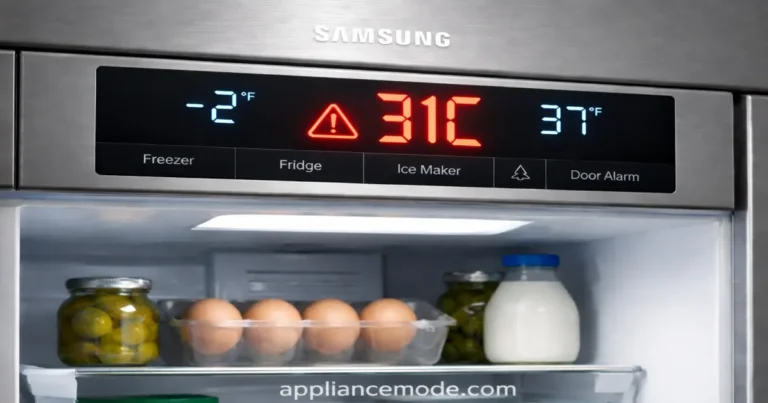
Most errors appear on the display or as blinking LED patterns on the control board or inverter board.
Before assuming a major fault, many issues can be fixed with simple steps like resetting the fridge, checking the door seal, or ensuring proper airflow.
Understanding Your Samsung Refrigerator Error Codes
Here are some common codes and what they generally mean:
Sensor Errors (Codes ending in C or E)
These codes often mean a temperature sensor isn’t working right. Sensors help your fridge know how cold it is inside different sections.
- 1C, 1E, or 1: Problem with the freezer sensor.
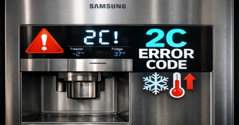
- 2C or 2E: Problem with the fridge sensor.
- 4C or 4E: Problem with the freezer defrost sensor.
- 5C or 5E: Problem with the fridge defrost sensor.
- 6C or 6E: Problem with the outside temperature (ambient) sensor.
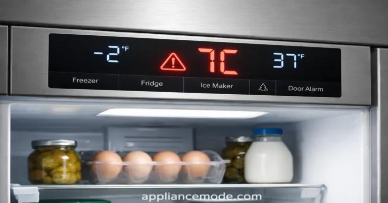
- 7C, 7E, 9C, or 9E: Problem with the pantry or Flex Zone sensor.
- 8C or 8E: Problem with the ice maker sensor.
- 11C or 11E: Problem with the Flex Zone defrost sensor.
- 13C or 13E: Problem with the general humidity sensor.
- 16C or 16E: Problem with the fridge humidity sensor.
What to Check (Sensor Errors):
- Check Connections: Sometimes, a wire is just loose. This usually requires accessing the main control board (often on the back or top), which can be tricky. If you’re not comfortable, skip this.
- Sensor Itself: The sensor might be faulty.
- Main Control Board: Less commonly, the main board that reads the sensor could be the issue.
For most sensor errors, if checking basic connections (if accessible) doesn’t help, the sensor or the main board likely needs to be replaced by a technician.
Fan Errors (Codes ending in C or E)
These codes point to issues with the fans that circulate cold air inside the fridge or cool parts like the condenser.
- 21C or 21E: Problem with the freezer fan.
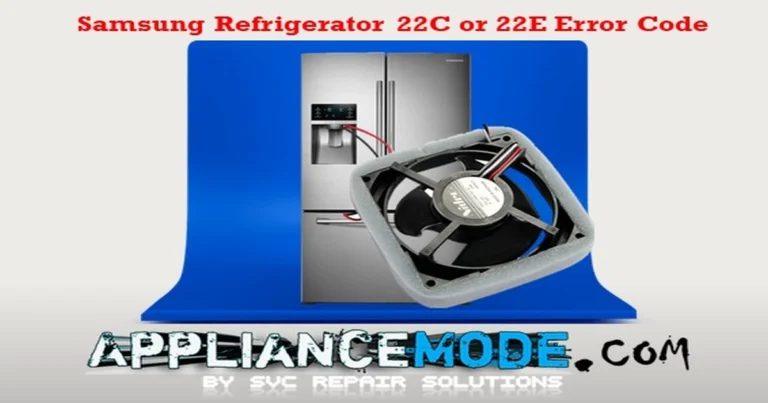
- 22C or 22E: Problem with the fridge fan.
- 23C or 23E: Problem with the condenser fan (usually located near the bottom back of the fridge).
- 31C or 31E: Problem with the Flex Zone fan.
- 62C or 62E: Problem with the pantry fan.
What to Check (Fan Errors):
- Look for Obstructions: Ice buildup or other items can block fan blades. Carefully check the area around the fan (in the freezer, fridge, or back of the unit) and clear any blockages after unplugging the fridge.
- Check Door Switch: Make sure the door switch is working correctly. Fans often turn off when the door is open. If the fridge thinks the door is open when it’s closed, it could cause fan issues.
- Fan Motor or Main Board: The fan motor itself might be bad, or there could be an issue with the main control board.
If clearing obstructions doesn’t fix the fan error, a technician will likely need to test the fan motor and the control board.
Defrost Errors (Codes ending in C or E)
Defrosting is when your fridge briefly warms up coils to melt away ice buildup. These errors mean this process isn’t happening correctly.
- 24C or 24E: Problem with the freezer defrost system.
- 25C or 25E: Problem with the fridge defrost system.
- 29C or 29E: Problem with the Flex Zone defrost system.
What to Check (Defrost Errors):
- Look for Excessive Ice: Significant ice buildup on the back wall of the freezer or fridge compartments can be a sign the defrost system is failing.
- Components Involved: The defrost system includes a heater, a sensor, and a thermostat (bimetal)—any of these could be faulty. The main board also controls this process.
If you see a lot of ice buildup and the error code is present, it’s best to call a technician to diagnose which defrost component needs replacing.
Ice Maker Errors (Codes ending in C or E)
These relate specifically to the ice-making function.
- 26C or 26E: General cubed ice maker function error.
- 33C or 33E: Problem with the ice maker heater (helps release ice).
- 116C, 116E, 117C, or 117E: Problem with the ice-bite maker function.
- 118C or 118E: Problem with the ice pipe heater (prevents the water line from freezing).
What to Check (Ice Maker Errors):
- Check for Ice Jams: Look inside the ice maker assembly for any stuck ice cubes or obstructions. Clear them after unplugging the fridge.
- Check Water Supply: Make sure the fridge has water supplied to the ice maker.
- Test Button: Many Samsung ice makers have a test button (often located on the ice maker assembly itself). Pressing this can force a cycle and help diagnose if it’s working.
- Components: The ice maker assembly, heaters, or main board could be faulty.
Clear any visible ice jams. If the problem persists, testing the specific components, like the heaters or the assembly itself, usually requires a technician.
Communication & Board Errors (Codes ending in C or E)
These codes suggest there’s a problem with how different electronic parts of the fridge are talking to each other.
- 41C or 44E: Problem with communication to the display panel.
- 44C, 44E, 45C, or 45E: Problem with communication between the main board and the inverter board (which controls the compressor).
- 46C or 46E: Internal communication error on the main board.
- 52C or 52E: Problem with the WiFi module communication.
What to Check (Communication & Board Errors):
- Power Cycle: Unplug the fridge for 10-15 minutes, then plug it back in. This can sometimes reset the electronics and clear temporary glitches.
- Check Connections: Like sensor errors, loose wires between the boards can cause this. This requires accessing internal components, so proceed with caution or call a technician.
- Faulty Boards: The main board, inverter board, or display board could be defective.
Power cycling is the main user step here. If the error returns, a technician will need to check connections and potentially replace electronic boards.
Compressor & Inverter Board Errors (Codes ending in C or E)
These are more serious errors related to the compressor (the heart of the cooling system) and the inverter board that controls it. Inverter board errors often have blinking lights on the board itself.
- 81C or 81E: Compressor failed to start.
- 82C or 82E: Problem detected with the inverter board (IPM fault).
- 83C or 83E: Abnormal electrical current detected at the compressor.
- 84C or 84E: Compressor motor is restricted or not running smoothly.
- 85C or 85E: Low voltage detected at the compressor.
- 86C or 86E: High voltage detected at the compressor.
- 96C or 96E: Compressor inverter board (IPM) shut down.
What to Check (Compressor & Inverter Errors):
- Power Cycle: Unplug the fridge for 10-15 minutes to attempt a reset.
- Faulty Parts: These errors almost always indicate a problem with the inverter board or the compressor itself.
These issues require professional diagnosis and repair. A technician is needed to safely test and replace these components.
Temperature & Other Errors
- 71C or 71E: Abnormally high freezer temperature.
- 72C or 72E: Abnormally high fridge temperature.
- 73C or 73E: Abnormally high Flex Zone temperature.
What to Check (High-Temperature Errors):
- Check the Doors: Make sure the doors are closing fully and aren’t blocked by food or other items. A door left open is a common cause!
- Hot Food: Avoid putting large amounts of hot food into the fridge or freezer.
- Clean Coils: Dirty condenser coils (usually on the back or underneath) can prevent the fridge from cooling efficiently. Clean them after unplugging the fridge.
- Cooling System Issues: If the problem persists, there might be an issue with the sealed cooling system (like a Freon leak) or other internal components, requiring a technician.
- 76C or 76E: AutoFill infuser overflow detected (for models with this feature).
- Check the infuser area for water. There might be an issue with the sensor or water valve.
- 77C or 77E: Camera error (for models with internal cameras).
- Check connections to the camera or the camera assembly itself. Might require service.
- 79C or 79E: Showcase heater error (for models with a showcase door).
- Problem with the heater that prevents condensation on the showcase door. Requires testing by a technician.
- OF, OF, O FF, or OFF: Demo mode or shop mode is active.
- This isn’t an error! It means the cooling is turned off for display purposes. Check your user manual for how to turn off demo mode (it usually involves pressing a combination of buttons).
Samsung Refrigerator Error Codes: Professional Troubleshooting Guide
This guide summarizes common error codes for Samsung RS, RH, and RF series refrigerators and outlines technical steps for diagnosis and repair.
CRITICAL SAFETY WARNING: Performing electrical tests and component replacements requires technical expertise and carries a risk of electric shock or damage to the appliance. Always disconnect power to the refrigerator before attempting any checks or repairs. If you are not a qualified technician, it is highly recommended to consult a professional.
| Samsung Refrigerator Error Codes | Meaning | Common Causes | Professional Troubleshooting Steps |
|---|---|---|---|
| Sensor Errors | |||
| 1C, 1E, 1 | Freezer Sensor Error | Open/Shorted sensor circuit, temperature out of range (-58°F/-50°C to +122°F/+50°C), Misplaced wires, Faulty sensor, Faulty main PCB | 1. Check sensor resistance at main PCB connector. Compare to the temp chart (e.g., ~5K Ohm @ 25°C/77°F). 2. Check voltage at the main PCB sensor connector (~1.6 Vdc @ 25°C/77°F). If it’s 0VDC, replace the main PCB. 3. Replace sensor if resistance/voltage is out of range. |
| 2C, 2E | Fridge Sensor Error | Open/Shorted sensor circuit, temperature out of range (-58°F/-50°C to +122°F/+50°C), Misplaced wires, Faulty sensor, Faulty main PCB | 1. Check sensor resistance at main PCB connector. Compare it to the temp chart (e.g., ~6K Ohm @ 20°C/68°F). 2. Check voltage at the main PCB sensor connector (~1.9 Vdc @ 20°C/68°F). If it’s 0VDC, replace the main PCB. 3. Replace sensor if resistance/voltage is out of range. |
| 4C, 4E | Freezer Defrost Sensor Error | Open/Shorted sensor circuit, temperature out of range (-58°F/-50°C to +122°F/+50°C), Faulty sensor, Faulty main PCB | 1. Check sensor resistance at main PCB connector. Compare it to the temp chart (e.g., ~13K Ohm @ 0°C/32°F). 2. Check voltage at main PCB sensor connector (~3Vdc @ 0°C/32°F). If it’s 0VDC, replace the main PCB. 3. Replace sensor if resistance/voltage is out of range. |
| 5C, 5E | Fridge Defrost Sensor Error | Open/Shorted sensor circuit, temperature out of range (-58°F/-50°C to +122°F/+50°C), Defective sensor, Defective main PCB | 1. Check sensor resistance at main PCB connector. Compare it to the temp chart (e.g., ~8.9K Ohm @ 10°C/50°F). 2. Check voltage at the main PCB sensor connector (~2.4 Vdc @ 10°C/50°F). If it’s 0VDC, replace the main PCB. 3. Replace sensor if resistance/voltage is out of range. |
| 6C, 6E | Ambient Sensor Error | Open/Shorted sensor circuit, Damaged sensor, Defective main PCB | 1. Check sensor resistance at main PCB connector. Compare to the temp chart (e.g., ~4.5K Ohm @ 28°C/82°F). 2. Check voltage at main PCB sensor connector (~1.5Vdc @ 28°C/82°F). If it’s 0VDC, replace the main PCB. 3. Replace sensor if resistance/voltage is out of range. |
| 7C, 7E, 9C, 9E | Pantry/Flex Zone Sensor Error | Open/Shorted sensor circuit, temperature out of range (-58°F/-50°C to +122°F/+50°C), Damaged sensor, Damaged main PCB | 1. Check sensor resistance at main PCB connector. Compare it to the temp chart (e.g., ~7K Ohm @ 16°C/60°F). 2. Check voltage at the main PCB sensor connector (~2Vdc @ 16°C/60°F). If it’s 0VDC, replace the main PCB. 3. Replace sensor if resistance/voltage is out of range. |
| 8C, 8E | Ice Maker Sensor Error | Open/Shorted sensor circuit, Temp out of range (-58°F/-50°C to +122°F/+50°C), Defective sensor, Defective main PCB | 1. Check sensor resistance at main PCB connector. Compare it to the temp chart (e.g., ~20.5K Ohm @ -10°C/14°F). 2. Check voltage at the main PCB sensor connector (~3.3 Vdc @ -10°C/14°F). If it’s 0VDC, replace the main PCB. 3. Replace sensor if resistance/voltage is out of range. |
| 11C, 11E | Flex Room Defrost Sensor Error | Open/Shorted sensor circuit, temperature out of range (-58°F/-50°C to +122°F/+50°C), Faulty sensor, Faulty main PCB | 1. Check for ice buildup in the compartment. 2. Check sensor resistance at main PCB connector. Compare to the temp chart (e.g., ~9.9K Ohm @ 7°C/45°F). 3. Check voltage at the main PCB sensor connector (~2.5 Vdc @ 7°C/45°F). If it’s 0VDC, replace the main PCB. 4. Replace sensor if resistance/voltage is out of range. |
| 13C, 13E | Humidity Sensor Error | Open/Shorted sensor circuit, temperature out of range (-50°C to +50°C), Broken sensor, Defective main PCB | 1. Visually inspect the sensor and check wire/housing connections. 2. Check sensor resistance. Compare it to the temp chart (e.g., ~2.6 Vdc @ 23°C/73°F, 60% RH). 3. If 0 Ohm (short) or ∞Ω/OL (open), replace the sensor. 4. Check voltage at main PCB connector. If it’s 0VDC, replace the main PCB. |
| 16C, 16E | Fridge Humidity Sensor Error | Open/Shorted sensor circuit, temperature out of range (-50°C to +50°C), Faulty sensor, Defective main PCB | 1. Check the sensor visually and check wire/housing connections. 2. Check sensor resistance. Compare it to the temp chart (e.g., ~2.6 Vdc @ 23°C/73°F, 60% RH). 3. If 0 Ohm (short) or ∞Ω/OL (open), replace the sensor. 4. Check voltage at main PCB connector. If it’s 0VDC, replace the main PCB. |
| Fan Errors | |||
| 21C, 21E | Freezer Fan Error | Corrosion on connector pins, Faulty fan, Faulty main PCB, Fan motor blocked, Door switch issue | 1. Check fan wire harness. 2. Check door switch operation. 3. Check fan motor voltage at the main PCB connector (~12 Vdc nominal). If it’s 0VDC, replace the main PCB. 4. Check fan feedback voltage at the main PCB (~2.6 Vdc nominal). If 0 VDC, check for blockage; if persistent, replace the fan motor. |
| 22C, 22E | Fridge Room Fan Error | Corrosion on connector pins, Faulty fan, Faulty main PCB, Fan motor blocked, Door switch issue | 1. Check wire harness between fan and main PCB. 2. Check door switch operation. 3. Check fan motor voltage at the main PCB connector (~12 Vdc nominal). If it’s 0VDC, replace the main PCB. 4. Check fan feedback voltage at the main PCB (~2.6 Vdc nominal). If 0 VDC, check for blockage; if persistent, replace the fan motor. |
| 23C, 23E | Condenser Fan Error | Broken wire harness, Faulty fan, Faulty main PCB, Fan motor blocked | 1. Check wire harness between fan and main PCB. 2. Check fan motor voltage at the main PCB connector (~12 Vdc nominal). If it’s 0VDC, replace the main PCB. 4. Check fan feedback voltage at the main PCB (~2.6 Vdc nominal). If 0 VDC, check for blockage; if persistent, replace the fan motor. |
| 31C, 31E | Flex Zone Fan Motor (CV-Fan) Error | Corrosion on connector pins, Faulty door switch, Loss of fan feedback signal, Faulty fan motor, Faulty main PCB | 1. Check fan motor resistance (∞Ω/OL or 0 ohm is a fault). 2. Check door switch. 3. Check fan motor voltage at the hinge connector (~12VDC nominal). If it’s 0VDC, replace the main PCB. 4. Check fan feedback voltage (~2.5 Vdc nominal). If 0 VDC, check for blockage; if persistent, replace the fan motor. |
| 62C, 62E | Pantry Fan Error | Corrosion on connector pins, Faulty fan motor, Faulty main PCB, Fan motor blocked | 1. Check wire harness between fan and main PCB. 2. Check fan motor voltage at the main PCB connector (~12 Vdc nominal). If it’s 0VDC, replace the main PCB. 3. Check fan feedback voltage at the main PCB (~2.6VDC nominal). If 0VDC, check for blockages. If persistent, replace the fan motor. |
| Defrost Errors | |||
| 24C, 24E | Freezer Defrost Error | Damaged wire harness, Heater circuit open/shorted, faulty main PCB, Defrost components (heater, bimetal, fuse) faulty | 1. Check for 120VAC from the main PCB connector to the heater. Initiate forced defrost (FD); voltage should drop to 0Vac. If voltage is present but no defrost, replace main PCB. If 120 VAC is not present, disconnect power. 2. At the main PCB, check the resistance of the heater, bimetal, and thermofuse circuit (~63 ohms total nominal). 3. If resistance is high/open, remove the evaporator cover and check the heater (~61 Ohm), bimetal (closed), and thermofuse (closed) individually. 4. Replace defective component or main PCB. |
| 25C, 25E | Fridge Defrost Heater Error | Defrost sensor failed to terminate after 1 hour, Faulty wire harness, Faulty thermo-fuse/bimetal/heater, Faulty main PCB | 1. Check heater resistance (~120 Ohm nominal). 2. Check bimetal continuity (should be closed). 3. Check thermal fuse continuity (should be closed). 4. Replace defective component. 5. Check and replace main PCB if necessary. |
| 29C, 29E | Flex Zone Defrost Control Error | Faulty Defrost Function, Faulty Heater, Misplaced wire/bimetal, Defective main PCB | 1. Run Forced Defrost (Fd). 2. Check heater voltage in case of a connector (~120 Vac). If there is no voltage, replace the main PCB. 3. Disconnect the red connector at the heater and check resistance (63-230 ohms). 4. Measure bimetal continuity. 5. Measure heater terminal continuity (replace if open/shorted). 6. Check F-Def Heater Fuse PCB Box continuity (replace if open). |
| Ice Maker Errors | |||
| 26C, 26E | Cubed Ice Maker Function Error | Faulty ice maker functions detected >3 times: Ice maker assembly issue | 1. Check door switch. 2. Check ice maker assembly for buildup/obstruction. 3. Press the ice maker test button to cycle. Replace assembly if test fails. 4. Check 12VDC on the IM motor clockwise pin after the test button press. If there’s no voltage, check the wire harness and main PCB. |
| 33C, 33E | Ice Maker Heater Error | Open heater circuit, Housing separation, Contact error, Disconnection, Short circuit, Faulty harness connector, Faulty heater, Faulty main PCB | 1. Disconnect the case connector and check the heater resistance (~135 ohms nominal). If 0 Ohm (short) or ∞Ω/OL (open/wire issue), diagnose/replace. |
| 116C, 116E, 117C, 117E | Ice Bites Maker Function Error | Faulty Ice Bites Maker Assembly | 1. Check wiring. 2. Check ice maker conditions. 3. Press the ice maker test switch. 4. Replace ice maker assembly. 5. Check/replace main board if error persists. |
| 118C, 118E | Ice Pipe Heater Error | Open heater connection, Housing separation, Short circuit, Faulty heater | 1. Check for ice blockage in the pipe. 2. Check DC voltage to water pipe heater at Main PCB CN90 (~7-12 VDC). 3. Check ice pipe heater resistance at main PCB (~62 Ohm nominal). 4. Press the ice maker test switch (for function check). |
| Communication & Board Errors | |||
| 41C, 44E | Display Communication Error | Faulty harness connector, Faulty Display Control Panel, Faulty main PCB | 1. Check display conditions. 2. Replace main PCB (as per original text’s sole solution). |
| 44C, 44E, 45C, 45E | Main PCB <=> Inverter PCB Communication Error | Loose communication, Defective inverter board, Connection wires issue, Defective main PCB | 1. Check for disconnected or shorted wires between the main PCB and the inverter PCB. 2. Check inverter PCB fuse continuity. 3. Replace main PCB or inverter PCB. 4. After replacing the inverter PCB, wait 5 minutes for the compressor restart. |
| 46C, 46E | Main PCB <=> I/O Expander Communication Error | Internal main PCB communication error | 1. Replace the main PCB (as per original text’s sole solution). |
| 52C, 52E | Main Wi-Fi Module Communication Error | Faulty WiFi Module, Main PCB issue | 1. Check for disconnected or shorted wires between the main PCB and the WiFi PCB. 2. Check for 12VDC at the WiFi module; if absent, replace the main PCB. 3. Replace the Wi-Fi module. |
| Compressor & Inverter Errors | |||
| 81C, 81E | Compressor Starting Failure (Inverter LED Blinks 1x) | Faulty harness connector, Faulty inverter PCB, Faulty compressor | 1. Power cycle unit (unplug 10 min). 2. Check for shorts between compressor terminals. 3. Check for shorts between IPM legs. 4. Check inverter PCB soldering. 5. Check compressor & cycle (compressor stops immediately, waits 5 min). 6. Replace inverter board or compressor if needed. |
| 82C, 82E | Compressor IPM Fault (Inverter LED Blinks 2x) | Compressor IPM failure detected, Faulty inverter board, Faulty compressor | 1. Check for shorts between compressor U/V/W and inverter PCB. 2. Check for shorts between IPM pins. 3. Check compressor & cycle (wait 5 min after replacing/resetting inverter). 4. Replace inverter board or compressor if needed. |
| 83C, 83E | Abnormal Current Pick-up at Compressor (LED Blinks 3x) | Abnormal current detected, Faulty inverter board, Faulty compressor | 1. Disconnect inverter PCB connector; check resistance between U/V/W wires (~12 Ohm nominal). 2. Check AC voltage (96-140 Vac nominal). 3. Check compressor & cycle (wait 5 min after replacing/resetting inverter). 4. Replace inverter board or compressor if needed. |
| 84C, 84E | Compressor Motor Restriction (Inverter LED Blinks 4x) | Compressor restricted > 5 sec, The compressor runs at < 1000 rpm > for 5 sec. Faulty inverter board, Faulty compressor | 1. Check inverter PCB connector. 2. Check compressor & cycle (wait 5 min after replacing/resetting inverter). 3. Replace inverter board or compressor if needed. |
| 85C, 85E | Low Voltage Compressor (Inverter LED Blinks 5x) | Low voltage detected at compressor, Faulty inverter board, Faulty compressor | 1. Check inverter connector. 2. Check compressor & cycle (wait 5 min after replacing/resetting inverter). 3. Replace inverter board or compressor if needed. |
| 86C, 86E | High Voltage Compressor (Inverter LED Blinks 6x) | High voltage detected at compressor, Faulty inverter board, Faulty compressor | 1. Check power to compressor U, V, and W connectors (should be less than 150 Vac). 2. Check compressor & cycle (wait 5 min after replacing/resetting inverter). 3. Replace inverter board or compressor if needed. |
| 96C, 96E | Compressor IPM Shut-down (Inverter LED Blinks 1x/2x) | Compressor IPM failure detected | 1. Check IPM temperature status on inverter PCB. 2. Check heat sink assembly status of IPM. 3. Check inverter PCB soldering. 4. Disconnect inverter PCB connector; check resistance between U/V/W wires (~12 Ohm nominal). 5. Check AC voltage (96-140 Vac nominal). 6. Replace inverter board or compressor if needed. |
| Temperature & Other Errors | |||
| 71C, 71E | Abnormal High Freezer Temperature | Door left open, Hot food stored, Dirty condenser coils, Faulty 3-way valve, Sealed system issue (leak, restriction) | 1. Ensure the door is closed and the seal is good. Remove hot food. 2. Check freezer sensor resistance vs. chart. 3. Clean condenser coils. 4. Diagnose sealed system or 3-way valve (requires technician). |
| 72C, 72E | Abnormal High Fridge Temperature | Door left open, Hot food stored, Dirty condenser coils, Faulty 3-way valve, Sealed system issue (leak, restriction) | 1. Ensure the door is closed and the seal is good. Remove hot food. 2. Check fridge sensor resistance vs. chart. 3. Clean condenser coils. 4. Diagnose sealed system or 3-way valve (requires technician). |
| 73C, 73E | Abnormally High Flex Zone Temperature | Door left open, Hot food stored, Dirty condenser coils, Faulty 3-way valve, Sealed system issue (leak, restriction) | 1. Ensure the door is closed and the seal is good. Remove hot food. 2. Clean condenser coils. 3. Diagnose sealed system or 3-way valve (requires technician). |
| 76C, 76E | AutoFill Infuser Overflow Error | Overflow sensor detects water, Sensor housing separation, Contact error, Disconnection, Short circuit, Faulty harness, Faulty sensor | 1. Check voltage at the main PCB (~5VDC is normal; 0-4.5VDC indicates overflow). 2. Check sensor housing, connections, and harness. 3. Replace sensor if faulty. |
| 77C, 77E | Camera Error | Faulty French assembly, Camera hardware failure, Unstable USB terminal (power noise) | 1. Check wire harness connector. 2. Check for 5VDC at the French Assy connector. 3. Check/replace the French Assyrian. 4. Address power noise issues. |
| 79C, 79E | Showcase Heater Error | Faulty harness connector, Faulty showcase heater | 1. Check harness connector. 2. Check showcase heater resistance (~14 Ohm nominal). |
| OF OF, O FF, OFF | Demo Mode Notification | Cooling mode activated for retail display | 1. This is not an error. Cooling is disabled. 2. Refer to the user manual to exit demo/shop mode (typically involves a button combination). |
Final Thoughts
Samsung refrigerator error codes are designed to help you quickly identify problems before they become major repairs. Whether the issue involves a temperature sensor, fan motor, defrost system, ice maker, communication fault, or cooling component, understanding what each code means can save valuable troubleshooting time and help you determine the best course of action.

I am a master appliance repair technician with over 35 years of experience in the field. I am passionate about helping people troubleshoot their appliances and fix common problems. My website, appliancemode.com, provides a wealth of information on troubleshooting common appliance issues and deciphering error codes. This website aims to empower people to tackle appliance repairs themselves and save money on service calls.