In this guide, we’ll explain how to use the Whirlpool refrigerator service diagnostic mode, what it does, and how it helps troubleshoot common cooling and system issues.
Most Whirlpool refrigerators use a built-in diagnostic system that allows technicians (and advanced users) to test individual components such as fans, sensors, dampers, defrost systems, and compressors without fully disassembling the appliance.
Whirlpool refrigerator troubleshooting using service diagnostic mode
Whirlpool refrigerator service diagnostic mode:
Service diagnostic mode refers to a mode of operation in electronic appliances where the system is specifically configured to allow for testing and troubleshooting of various components and functions. This mode typically provides access to advanced diagnostic tools and information that can assist technicians in determining the cause of problems and making repairs.
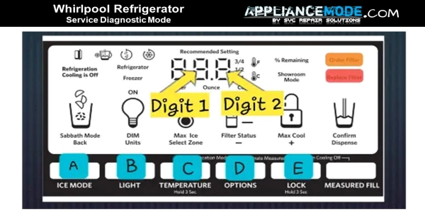
Entering service diagnostic mode:
Ensure that the unit is not in the control lock function before entering service diagnostic mode.
Press buttons A and B at the same time for 3 seconds.
Release both buttons once the 3, 2, 1 countdown is complete.
The display will show “01” to confirm that you are in the first step of the diagnostic process.
Exiting service diagnostic mode:
To exit the service diagnostics mode at any time, use one of the following two methods:
Method 1: Press buttons A and B together for 3 seconds.
Method 2: Unplug the appliance from power.
Two things to keep in mind:
Manual progression is required for each step.
Use the E button to move to the next step or skip it.
Use the D button to return to a previous step.
Use the C button to control the components to be tested. (e.g., fan motors, heater, compressor speed, etc.)
The step number and results are shown in the two digits on the user interface.
The display will show an orange light during the step number.
The display will show a red light during the step results.
Whirlpool refrigerator troubleshooting: Test cycle steps
Step 01: Freezer compartment sensor test
The unit will check the condition of the freezer cabinet sensor and display the result on the temperature section.
Function behavior:
Step result:
Possible outcomes:
Meaning
01
The sensor is in good condition.
02
NTC open circuit: faulty sensor
03
NTC closed circuit: faulty sensor
A guide on how to check a faulty freezer compartment sensor:
Check the wire harness between the FC sensor and the main board.
If there are any loose or cut wire connections or short leads, repair and/or replace the harness.
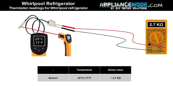
Check the thermistor’s resistance according to the sensor temperature chart. If the resistance is not within the specified range, replace the sensor.
Electric part name
Temperature
Ohmic value
FC thermistor
25°C | 77°F
~ 2.7 KΩ
Freezer sensor temperature chart
Thermistor readings for Whirlpool refrigerator
Step 02: Refrigerator compartment sensor test
The unit will measure the ohmic value of the refrigerator cabinet sensor and display the result on the temperature section.
Function behavior:
Step result:
Possible outcomes:
Meaning
01
The sensor is in good condition.
02
NTC open circuit: faulty sensor
03
NTC closed circuit: faulty sensor
A guide on how to check a faulty refrigerator compartment sensor:
Check the wire harness between the RC sensor and the main board.
If there are any loose or cut wire connections or short leads, repair and/or replace the harness.
Measure the resistance of the thermistor using the sensor temperature chart. If the resistance is not within the specified range, replace the sensor.
Electric part name
Temperature
Ohmic value
RC thermistor
25°C | 77°F
~ 2.7 KΩ
Refrigerator sensor temperature chart
Step 03: Evaporator fan motor and air baffle motor test
The unit will be compelled to operate both the freezer and refrigerator fans and the air baffle motor.
Function behavior:
Step results:
Possible outcomes:
Meaning
01
Both fan motors are off.
By pressing the C button, 02 will appear.
The freezer fan will turn on.
By pressing the C button one more time, 03 will appear.
Activation of the refrigerator compartment fan. The pantry air damper will function automatically. 13: indicates damper open. 23: indicates the damper is closed.
By pressing the C button one more time, 04 will appear.
Both fan motors will turn on.
A guide on how to check the possible outcomes:
02: The freezer fan will turn on.
Verify the functioning of the evaporator fan by opening the freezer door and feeling for airflow with your hand. If no airflow is present,
Check the fan motor wire harness.
Check the fan blade.
Check the FC fan motor voltage.
Electric part name
Voltage value
Feedback voltage value
FC fan motor
13.2 Vdc
2.6 Vdc
03: The pantry air damper will function automatically.
To confirm the air flow inside the pantry, inspect the left side when the damper is open and the display reads 13.
If no airflow is present, check the damper wire harness, inspect the damper motor for any blockage (stuck closed), and replace it if necessary.
The air flow in the pantry will stop when the display shows 23.
If airflow is present, check the damper wire harness, inspect the damper motor for any blockage (stuck open), and replace it if necessary.
04: Both fan motors will turn on.
Verify the functioning of the evaporator fan by opening the freezer door and feeling for airflow with your hand. (Same as refrigerator compartment) If no airflow is present,
Check the fan motor wire harness.
Check the fan blade.
Check the fan motor voltage test point:
Electric part name
Voltage value
Feedback voltage value
FC fan motor
13.2 Vdc
2.6 Vdc
RC fan motor
13.2 Vdc
2.6 Vdc
Step 04: Compressor, condenser, and evaporator fan test
The unit requires activation of both the condenser and evaporator fans, as well as the compressor. A 3-second pause is implemented prior to initiation, serving as a warning to the technician that this test will take approximately 10 minutes with no option for interruption. If proceeding with the test is not desired, skip it by pressing the E button before the 3 seconds elapse. If no action is taken, the test will commence automatically once the 3 seconds expire.
Function behavior:
Step results:
Functional status outcomes
Meaning
01
Begin by setting the dual evaporator valve to its default position. Note: It should take 4 minutes to complete the operation.
02
Close both the freezer and refrigerator evaporator valves. Note: It should take 1 minute to complete the operation.
03
compressor starting. Note: It should take 1 minute to complete the operation.
04
The compressor keeps running, the valve switches to the refrigerator position, and the RC evaporator fan is activated.
05
The compressor keeps operating, the valve changes freon flow to the freezer position, and the FC evaporator fan is activated.
The condenser fan should always be running when the compressor is on.
Guide on how to check the functional status outcomes:
03: Compressor starting.
Verify the compressor’s functionality by placing your hand on it and feeling for vibrations “to ensure that the compressor is working properly.”
A lack of vibrations could indicate a problem with the compressor.
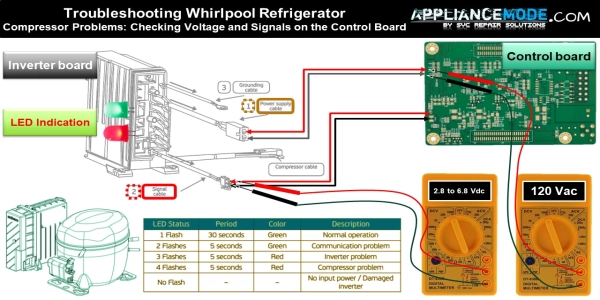
Check the wire harness connection between the main board and the inverter board.
Check the wire harness connection between the compressor and inverter board.
Check the inverter board compressor voltage test point:
Voltage: main voltage
PWM voltage value: speed controller voltage.
Electric part name
Voltage value
PWM voltage value
Inverter board
115 Vac
~ 2.8–6.8 Vdc
If any voltage is missing, replace the main board; if it is present, then replace the inverter board and move on to the next step.
Troubleshooting Whirlpool Refrigerator Compressor Problems: Checking Voltage and Signals on the Control Board
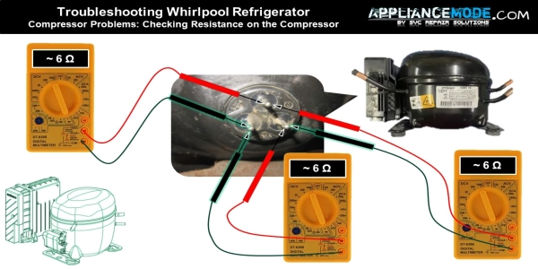
Electric part name
Ohmic value between U, V and W
Compressor
~ 6 Ω
Check the compressor’s resistance using an ohmmeter.
Troubleshooting Whirlpool Refrigerator Compressor Problems: Checking Resistance on the Compressor
04: The compressor keeps running, the valve switches to the refrigerator position, and the RC evaporator fan is activated.
Check the RC fan rotation.
Verify refrigerant flow into the evaporator by taking off the rear panel. When the display reads 04, check the temperature of the evaporator coil inlet with your hand. If you feel a chill, then the 3-way valve is functioning properly. However, if not:
Check the wire harness between the dual-evaporator valve and the main board.
Check the 3-way valve stepper motor resistance.
Restricted capillary…
Flush the refrigeration-sealed system and/or replace the cap tube or both.
Freon leak, heavy repair could be necessary.
Find the leak! Repair it and recharge the appliance with an appropriate refrigerant.
05: The compressor keeps operating, the valve changes freon flow to the freezer position, and the FC evaporator fan is activated.
Follow the same steps mentioned above.
Step 05: Compressor speed test
Function behavior:
Step result:
Possible outcomes:
Meaning
02
medium-speed
By pressing the C button, 03 will appear.
The compressor starts at medium and increases to full speed. Upon reaching full speed, “01” is displayed.
By pressing the C button one more time, 04 will appear.
Speed decreases from full to medium; when medium speed is reached, “02” is displayed.
Step 06: Defrost heater, bimetal, and sensor test
Function behavior:
Step result:
Possible outcomes:
Meaning
01
Bimetal Closed
02
Bimetal Open
A guide on how to check a faulty defrost bimetal:
Check the wire harness between the bimetal sensor and the main board.
If there are any loose or cut wire connections or short leads, repair and/or replace the harness.
Check the thermal-fuse resistance.
Measure the resistance of the bimetal using the table below. If the resistance is not within the specified range, replace the bimetal.
Electric part name
Temperature
Ohmic value
Abnormal value
Bi-metal
6°C | 42°F
~ ∞ Ω | OL
~ 0.1 – 2.1 Ω
Bi-metal
-11°C | 12°F
~ 0.1 – 2.1 Ω
~ ∞ Ω | OL
Defrost heater
–
~ 30 Ω
~ 0.1 – 2.1 Ω | ∞ Ω | OL
Defrost heater resistance and bi-metal temperature chart
Step 07: Defrost mode
In Adaptive Defrost Control (ADC) mode, the system initiates a defrost cycle after the compressor has accumulated a specific runtime. A microprocessor continuously monitors this runtime and adjusts the interval between subsequent defrost cycles. This adaptive adjustment is based on the duration of each defrost cycle, specifically the time elapsed between the activation of the defrost heater and the opening of the defrost thermostat.
In basic mode, the defrost cycle takes place every 8 hours for approximately 27 minutes.
Function behavior:
Step result:
Functional status outcomes
Meaning
01
Default setting: ADC ON
02
Basic mode ON
Note: The value will be saved in EEPROM, and the Defrost Mode will be initialized based on this setting during the next power-up.
Step 08: Display test
Function behavior:
All LED indicators and display digits will turn on automatically.
Step 11: Dispenser Led setting
Each time you press the C button, the dispenser’s brightness setting changes in this way:
Brightness: 0%
Brightness: 100%
Brightness: 50%
Step 15: Ice Level Sensor test
Function behavior:
Step result:
Possible outcomes:
Meaning
01
Bin full
02
Bin not full
Step 16: Freezer compartment door switch test.
Function behavior:
Step result:
Possible outcomes:
Meaning
02
Door Closed
01
It occurs when the door is opened.
Step 17: Refrigerator compartment door switch test
Function behavior:
Step result:
Possible outcomes:
Meaning
02
Door Closed
01
It occurs when the door is opened.
Step 18: Ice door motor test
Function behavior:
Step results:
Possible outcomes:
Meaning
01
Closed
02
Opening
03
open
04
Closing
Step 19: Ice maker fill tube heater status
Function behavior:
Step result:
Possible outcomes:
Meaning
01
ON
By pressing the C button, 02 will appear.
OFF
A guide on how to check a faulty ice maker fill tube heater:
Check the wire harness between the ice maker fill tube heater and the main board.
If there are any loose or cut wire connections or short leads, repair and/or replace the harness.
Measure the resistance of the ice maker fill tube heater. using your multimeter.
Electric part name
Ohmic value
Abnormal value
Ice maker fill tube heater
~ 870–2700 Ω
~ 0.1 – 2.1 Ω | ∞ Ω | OL
Step 32: Ambient sensor test
The unit will measure the ohmic value of the ambient sensor and display the result on the temperature section.
Function behavior:
Step result:
Possible outcomes:
Meaning
01
The sensor is in good condition.
02
NTC open circuit: faulty sensor
03
NTC closed circuit: faulty sensor
A guide on how to check a faulty ambient sensor:
Check the wire harness of the ambient thermistor.
If there are any loose or cut wire connections or short leads, repair and/or replace the harness.
Measure the resistance of the thermistor using the sensor temperature chart. If the resistance is not within the specified range, replace the sensor.
Electric part name
Temperature
Ohmic value
Ambient thermistor
25°C | 77°F
~ 2.7 KΩ
Ambient temperature chart.
Step 33: Humidity sensor test
The unit will check the room RH% and display the result in the temperature section.
Function behavior:
Step result:
Possible outcomes:
Meaning
Humidity value: xx%
The sensor is in good condition.
Er
Faulty sensor.
A guide on how to check a faulty humidity sensor:
Check the wire harness of the humidity thermistor.
If there are any loose or cut wire connections or short leads, repair and/or replace the harness.
Measure the voltage of the thermistor using a multimeter.
Electric part name
RH %
voltage value
Humidity thermistor
~ 65% @ 77°F
~ 2.4 Vdc
Note: Unplug the refrigerator before servicing
Step 36: Ice box fan test
The unit will be compelled to operate an ice box fan.
Function behavior:
Step results:
Possible outcomes:
Meaning
01
Fan motor ON
By pressing the C button, 02 will appear.
Fan motor OFF
A guide on how to check the possible outcomes:
01: The ice box fan is turned on.
Verify the functioning of the I.B. fan by feeling the airflow with your hand. If no airflow is present,
Check the fan motor wire harness.
Check the fan blade.
Check the I.B. fan motor voltage on the main board:
Electric part name
Voltage value
Feedback voltage value
I.B fan motor
13.2 Vdc
2.6 Vdc
Step 37: Ice box sensor test
The unit will measure the ohmic value of the icebox sensor and display the result on the temperature section.
Function behavior:
Step result:
Possible outcomes:
Meaning
01
The sensor is in good condition.
02
NTC open circuit: faulty sensor
03
NTC closed circuit: faulty sensor
A guide on how to check a faulty ice box sensor:
Check the wire harness of the I.B. thermistor.
If there are any loose or cut wire connections or shorted leads, repair and/or replace the harness.
Measure the resistance of the thermistor using the sensor temperature chart. If the resistance is not within the specified range, replace the sensor.
Electric part name
Temperature
Ohmic value
I.B thermistor
25°C | 77°F
~ 2.7 KΩ
Ice box sensor temperature chart
Step 38: Forced defrost mode
Forced defrost mode is a function in refrigerators that allows the user to manually initiate the defrost cycle. During this cycle, the compressor and fans are temporarily turned off, and the built-up ice on the evaporator coils is melted and drained.
Function behavior:
Step result:
Possible outcomes:
Meaning
SH
Short defrost
LO
Long defrost
Step 39: Refrigerator evaporator sensor test.
The unit will measure the ohmic value of the RC evaporator sensor and display the result on the temperature section.
Function behavior:
Step result:
Possible outcomes:
Meaning
01
The sensor is in good condition.
02
NTC open circuit: faulty sensor
03
NTC closed circuit: faulty sensor
A guide on how to check a faulty refrigerator evaporator sensor:
Check the wire harness of the RC evaporator thermistor.
If there are any loose or cut wire connections or short leads, repair and/or replace the harness.
Measure the resistance of the thermistor using the sensor temperature chart. If the resistance is not within the specified range, replace the sensor.
Electric part name
Temperature
Ohmic value
RC evaporator thermistor
25°C | 77°F
~ 2.7 KΩ
RC evaporator sensor temperature chart.
Step 45: Ice maker water fill test
Prior to starting the test, proceed to step 57 to initiate the ice maker harvest to ensure that all ice has been cleared from the mold. Next, once step 45 has been reactivated, wait for 3 seconds, and the water fill status of the ice maker will be displayed on the user interface.
Function behavior:
Step result:
Possible outcomes:
Meaning
02
Off.
By pressing the C button, 03 will appear.
Fill with water.
By pressing the C button one more time, 04 will appear.
The water filling is paused.
A guide on how to check for possible outcomes:
Fill status 02: water filling is off.
This step requires the water to remain inactive, but if it fails to do so, there may be an issue with the appliance. To resolve this:
Inspect the IM water inlet valve for any physical damage (the inlet valve cannot shut off the water) and replace it if necessary.
It is possible that the main board is continuously providing voltage, causing the valve to remain energized (due to a faulty relay or TRIAC stuck closed). In this case, inspect the main board and replace it if needed.
Fill status 03: Fill with water.
This step requires the water to remain active, but if it fails to do so, there may be an issue with the appliance. To resolve this:
Check the water valve wire harness connection.
Check and/or replace the water filter, filter head, and tube assembly.
Frozen water line: Check the ice maker water line.
Check the inlet valve resistance.
Electric part name
Ohmic value
Ice maker water inlet valve
~ 1.4 KΩ
Step 46: Water dispensing test
Function behavior:
Step result:
Possible outcomes:
Meaning
00
Off.
02
Fill with water.
A guide on how to check for possible outcomes:
Follow the same steps as in test 45: Fill with water (possible outcome #03).
Check the water reservoir (frozen, clogged, etc.)
Check the water dispenser switch contact.
Electric part name
Ohmic value
Dispenser water inlet valve
~ 1.4 KΩ
Check the dispenser water inlet valve resistance.
Step 56: Ice maker error codes
Function behavior:
Possible outcomes:
Error codes
Meaning
E0
The ice maker is functioning properly, and no action is required!
E1
Cooling issue: the ice maker timed out due to an inability to reach the desired temperature. Possible fan or cooling problem.
E2
Home Position Loss: Ice Maker Failed to Find Position During Harvest
E3
Heater Time-Out: The ice mold heater was on for too long.
E4
Dry Cycle Issues: Unit Experienced Dry Cycles Above Minimum Requirement
E5
Faulty Ice Maker Thermistor
A guide on how to check for possible outcomes:
E1: Check the ice box fan (refer to Test 36) or sealed system that is malfunctioning.
E2: Check if the ice maker is frozen and unable to rotate in both directions. If so, proceed to Test 58 and perform an IM defrosting test, then recheck. If this is not the issue, move on to Test 59. If x”2″ (x = Digit 1 and 2 = Digit 2) displays in the test result, replace the ice maker assembly.
E3: Move on to Test 58 and check the IM heater.
E4: Check the IM fill valve (refer to Test 45).
E5: Check the ice maker sensor, proceed to Test 58, and perform an ice maker thermistor test if x”2” (x = Digit 1 and 2 = Digit 2) or x”3” (x = Digit 1 and 3 = Digit 2) displays in the test result.
Check the wiring harnesses.
Check the thermistor and replace it if necessary.
If the error still occurs, replace the IM assembly.
Step 57: Ice maker harvest
Function behavior:
Step result: Digit 1.
Test sequence
Meaning
0
The heater and motor are off.
By pressing the C button, 01 will appear.
The ice maker heater is on.
By pressing the C button one more time, 02 will appear.
The motor rotates CW until it finds its home position.
Step result: Digit 2.
Possible outcomes:
Meaning
0
In Progress.
1
Harvesting Completed.
2
Harvesting is not complete; doors must be closed.
Step 58: Ice maker heater and thermistor test
Function behavior:
Step result: Digit 1.
Test sequence
Meaning
0
The IM heater is off.
By pressing the C button, 01 will appear.
The IM heater is on.
Step result: Digit 2.
Possible outcomes:
Meaning
0
The temperature is warmer than the harvest temperature.
1
The temperature is cooler than the harvest temperature.
2
NTC open circuit: faulty sensor
3
NTC closed circuit: faulty sensor
Step 59: Ice maker motor test
Function behavior:
Step result: Digit 1.
Test sequence
Meaning
0
Motor OFF
By pressing the C button, 01 will appear.
Motor Rotating CW until home position
By pressing the C button one more time, 02 will appear.
Motor OFF
By pressing the C button one more time, 03 will appear.
Motor rotating CCW until home position.
Step result: Digit 2.
Possible outcomes:
Meaning
0
In Progress.
1
Harvesting Completed.
2
Harvesting is not complete.
Step 65: Pantry thermistor test
Function behavior:
Step result:
Possible outcomes:
Meaning
01
The sensor is in good condition.
02
NTC open circuit: faulty sensor
03
NTC closed circuit: faulty sensor
A guide on how to check a faulty pantry sensor:
Check the wire harness of the pantry thermistor.
If there are any loose or cut wire connections or short leads, repair and/or replace the harness.
Measure the resistance of the thermistor using an ohmmeter.
Electric part name
Temperature
Ohmic value
Pantry thermistor
25°C | 77°F
~ 2.7 KΩ
Step 73: Pantry heater status
Function behavior:
Step result:
Possible outcomes:
Meaning
01
The pantry heater is on
02
The pantry heater is off
Step 77: Defrost thermistor test
Function behavior:
Step result:
Possible outcomes:
Meaning
01
The sensor is in good condition.
02
NTC open circuit: faulty sensor
03
NTC closed circuit: faulty sensor
A guide on how to check a faulty defrost sensor:
Check the wire harness of the defrost thermistor.
If there are any loose or cut wire connections or short leads, repair and/or replace the harness.
Measure the resistance of the thermistor with an ohmmeter.
Electric part name
Temperature
Ohmic value
Defrost thermistor
25°C | 77°F
~ 2.7 KΩ
Final Thought
The Whirlpool refrigerator service diagnostic mode is a powerful troubleshooting tool that helps identify issues in cooling, airflow, defrosting, and sensor systems. Instead of guessing faulty parts, it allows you to test each component individually, making repairs faster and more accurate. When used correctly, it can significantly reduce diagnostic time and help restore proper refrigerator performance efficiently.
I am a master appliance repair technician with over 35 years of experience in the field. I am passionate about helping people troubleshoot their appliances and fix common problems. My website, appliancemode.com, provides a wealth of information on troubleshooting common appliance issues and deciphering error codes. This website aims to empower people to tackle appliance repairs themselves and save money on service calls.
This guide doesn’t say which test goes with which step (I’m looking in the ice box section). I’d like to love this guide but it’s missing crucial information.


This guide doesn’t say which test goes with which step (I’m looking in the ice box section). I’d like to love this guide but it’s missing crucial information.