
How to Fix Samsung Refrigerator Error Code 85C: Compressor Under Voltage Troubleshooting Guide
How to Fix Samsung Refrigerator Error Code 85C: Compressor Under Voltage Troubleshooting Guide
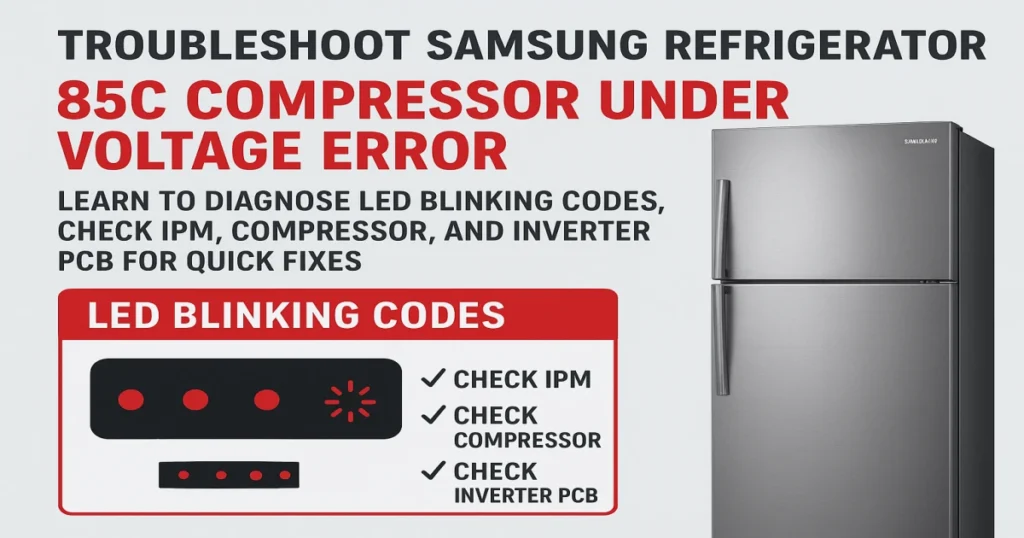
Error Code 85C on a Samsung refrigerator typically points to a fault in the inverter control board that drives the compressor, often related to power supply issues. When the system detects the compressor is running on insufficient voltage, it triggers a protective shutdown. Follow the steps below to diagnose and resolve this issue.
Step 1: Immediate Action and System Reset
When the refrigerator detects a failure condition, it initiates a protective cool-down period.
- Stop and Wait: If the failure is detected while the compressor is operating, the system will stop the compressor immediately and wait for 5 minutes.
- Standby Mode: During this 5-minute standby time, the RPM command signal is disabled. Even if the main board sends a signal for the compressor to run, it will not start.
- Status Indicator: In the standby state (or another specific non-error state), the LED on the inverter board may be tuned on for 1 second and then off for 2 seconds.
After the 5-minute standby period, the system will attempt to restart or display a persistent error via the LED blinking pattern.
Step 2: Specific Under Voltage Checks (5 Short Flashes)
The error you are targeting, Under Voltage, is specifically indicated by 5 short LED flashes followed by a pause. The primary causes are related to the main power supply or DC link components.
| Protecting Function | LED Blinking Frequency | Primary Cause / Action |
| Under Voltage | 5 Short Flashes | 1. Check Input Voltage: Verify the input voltage is not dropping under AC 53V at the inverter board, which is too low for operation. |
| 2. Check DC Link Resistor: Check for a short circuit in resistor R312 (the DC link resistor) on the inverter PCB. |
Step 3: General Inverter and Compressor Diagnostics
The general checks below should be performed regardless of the blinking code, as they cover common faults that often accompany or mimic an under-voltage issue, such as a Starting Failure (1 Flash) or IPM Fault (2 Flashes).
A. Checking Compressor and IPM (Intelligent Power Module)
These checks address potential issues with the component that drives the compressor (the IPM) and the compressor itself.
- Check Compressor Terminals: Check for a short circuit between the compressor terminals (U, V, and W phases). A short here typically results in a Starting Failure (1 flash).
- Check IPM Pins: Check if there is a short between IPM Pins (often Pins #1 through #26 or #1 through #33, depending on the model).
- Check IPM Voltage: Verify the IPM Operating Voltage is not dropping under DC 13.5V. A voltage drop below this threshold is a direct cause of a Starting Failure (1 flash).
- Check the Compressor and the Cycle: If electrical components seem fine, the compressor itself may be mechanically locked, or there may be an issue with the refrigeration cycle (e.g., severe restriction or overload).
B. Checking the Inverter PCB
- Check Soldering Status: Visually inspect the Inverter PCB for any signs of poor soldering, cold joints, or components that may have short-circuited (e.g., around resistor R1 which is cited as a cause for IPM Fault).
Full Troubleshooting Reference: LED Blinking Frequency Chart
If the failure condition persists after 5 minutes, the LED will blink according to the fault detected. Refer to this comprehensive chart for all potential error codes related to the inverter board.
| LED Blinking Frequency | Protecting Functions | Remarks (Possible Causes / Action) |
| Solid Red | Normal Operation | N/A |
| 1 Short Flash | Starting Failure | 1. Short between COMP U, V, and W phase (CN04). 2. Short among IPM Pins (No. #1 ~ 26). 3. Drop the IPM operating voltage under DC 13.5V. 4. Other cases, check the COMP, cycle, etc. |
| 2 Short Flashes | IPM Fault | 1. Open the COMP wire (CN04). 2. Bad condition of R1 (ex. Bad soldering). 3. Other cases, check the COMP, cycle, etc. |
| 3 Short Flashes | Abnormal Current Detection | 1. Operating the locked rotor COMP within 5 seconds. 2. Operating the COMP under 1000 RPM more than 5 seconds. 3. Occur the huge change of input voltage in a moment. 4. Other cases, check the COMP, cycle, etc. |
| 4 Short Flashes | Motor Locked / Over RPM | 1. Operating the locked rotor COMP within 5 seconds. 2. Operating the COMP under 1000 RPM more than 5 seconds. 3. Occur the huge change of input voltage in a moment. 4. Other cases, check the COMP, cycle, etc. |
| 5 Short Flashes | Under Voltage | 1. Drop the input voltage under AC 53V. 2. Short resistor R312 (DC link resistor). |
| 6 Short Flashes | Over Voltage | 1. Increase the input voltage over AC 155V. 2. Short resistor among R309, R310 and R311. (DC link resistor). |

I am a master Appliance Repair technician with over 35 years of experience in the field. I am passionate about helping people troubleshoot their appliances and fix common problems. My website, appliancemode.com, provides a wealth of information on troubleshooting common appliance issues and deciphering error codes. This website aims to empower people to tackle appliance repairs themselves and save money on service calls.