
Samsung Refrigerator 8-Segment Error Codes
The Samsung refrigerator 8-sugment diagnostic mode displays error information through the refrigerator’s LED indicators. These diagnostic codes help technicians identify problems with temperature sensors, evaporator fans, defrost heaters, ice makers, communication circuits, and the inverter compressor system.
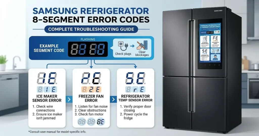
This guide explains the Samsung refrigerator Segment 8 error codes, their possible causes, and recommended testing procedures for identifying faulty components.
Samsung Refrigerator 8-Segment Error Codes: Complete Troubleshooting Guide
1. Fridge LED Error Codes
The following errors relate to the refrigerator compartment, ice maker, pantry section, and water reservoir heating system.
I/M-SENSOR (R on Twin I/M Units)
Error: Ice Maker Sensor Error

Possible Causes:
- Open or short circuit in the ice maker sensor.
- Loose, damaged, or disconnected sensor connector.
- Abnormal temperature reading above 122°F (50°C) or below -58°F (-50°C).
Testing Procedure: Measure the sensor voltage at the MAIN PCB. The expected voltage should be between 1.0V and 4.5V.
R-SENSOR
Error: Refrigerator Compartment Sensor Error

Possible Causes:
- Open or short circuit in the refrigerator temperature sensor.
- Loose or defective sensor connector.
- Temperature reading above 122°F (50°C) or below -58°F (-50°C).
Testing Procedure: Check the sensor voltage at the MAIN PCB. The expected voltage range is 1.0V–4.5V.
DEFROST SENSOR OF R ROOM
Error: Refrigerator Defrost Sensor Error

Possible Causes:
- Open or short circuit in the refrigerator defrost sensor.
- Loose or damaged connector.
- Temperature reading outside the specified range of -58°F to 122°F (-50°C to 50°C).
Testing Procedure: Measure the sensor voltage at the MAIN PCB. It should be between 1.0V and 4.5V.
R-FAN ERROR
Error: Refrigerator Evaporator Fan Error

Possible Causes:
- The refrigerator evaporator fan is not operating at the correct RPM.
- Fan motor malfunction.
- Open circuit in the fan feedback signal.
- Wiring or connector failure.
Testing Procedure: Check the fan voltage at the MAIN PCB. The expected voltage should be between 7V and 12V.
I/M FUNCTION ERROR (R on Twin I/M Units)
Error: Ice Maker Operation Error

Possible Causes: The ice tray fails to return to its normal level after completing an ice-harvesting cycle. This error is displayed after three unsuccessful attempts.
Recommended Action: Inspect the ice maker assembly and its mechanical operation. If the ice maker is defective, replace the ice maker assembly.
R-DEFROSTING ERROR
Error: Refrigerator Defrost Heater Error

Possible Causes:
- Open or short circuit in the refrigerator defrost heater.
- Defective heater connector or wiring.
- Faulty temperature fuse or bi-metal thermostat.
- Defrost operation exceeds 80 minutes.
Testing Procedure: Disconnect the defrost heater connector from the PCB and measure the heater resistance. Also inspect the temperature fuse, bi-metal thermostat, wiring, and connectors.
PANTRY-DAMPER-HEATER ERROR
Error: Pantry Damper Heater Error

Possible Causes: A fault is detected in the pantry compartment sensor/heater system.
Testing Procedure: Disconnect the heater connector from the PCB and measure its resistance. Inspect the associated wiring and connector for damage.
PANTRY-SENSOR ERROR
Error: Pantry Compartment Sensor Error

Possible Causes:
- Open or short circuit in the pantry (CR room) temperature sensor.
- Loose or defective sensor connector.
- Temperature reading above 122°F (50°C) or below -58°F (-50°C).
Testing Procedure: Measure the sensor voltage at the MAIN PCB. The expected voltage range is 1.0V–4.5V.
WATER HEATER ERROR
Error: Water Reservoir Heater Error

Possible Causes: The error appears when the water reservoir tank heater circuit is open or shorted.
Testing Procedure: Disconnect the water heater connector from the PCB and measure the heater resistance. Inspect the wiring and connector for damage.
2. Freezer LED Error Codes
These diagnostic errors relate to the freezer compartment, evaporator fans, condenser fan, French door ice room, and freezer defrost system.
EXT-SENSOR
Error: Ambient Temperature Sensor Error

Possible Causes:
- Open or short circuit in the external temperature sensor.
- Loose or damaged sensor connector.
- Temperature reading above 122°F (50°C) or below -58°F (-50°C).
Testing Procedure: Check the sensor voltage at the MAIN PCB. The expected voltage should be between 1.0V and 4.5V.
F-SENSOR
Error: Freezer Compartment Sensor Error

Possible Causes:
- Open or short circuit in the freezer temperature sensor.
- Defective or disconnected sensor connector.
- Temperature reading outside the specified range of -58°F to 122°F (-50°C to 50°C).
Testing Procedure: Measure the sensor voltage at the MAIN PCB. The expected voltage range is 1.0V–4.5V.
F-DEF-SENSOR
Error: Freezer Defrost Sensor Error.

Possible Causes:
- Open or short circuit in the freezer defrost sensor.
- Loose or defective sensor connector.
- Abnormal temperature reading above 122°F (50°C) or below -58°F (-50°C).
Testing Procedure: Check the sensor voltage at the MAIN PCB. The expected voltage should be between 1.0V and 4.5V.
F-FAN ERROR
Error: Freezer Evaporator Fan Error

Possible Causes:
- The freezer evaporator fan is not operating at the correct RPM.
- Defective fan motor.
- Open fan feedback circuit.
- Wiring or connector failure.
Testing Procedure: Measure the fan voltage at the MAIN PCB. The expected voltage should be between 7V and 12V.
C-FAN ERROR
Error: Condenser Fan Error

Possible Causes:
- The condenser fan is not rotating at the correct RPM.
- Defective condenser fan motor.
- Open circuit in the fan feedback line.
- Damaged wiring or connector.
Testing Procedure: Check the fan voltage at the MAIN PCB. The expected voltage should be between 7V and 12V.
FRENCH DOOR ICE ROOM SENSOR
Error: French Door Ice Room Temperature Sensor Error

Possible Causes:
- Open or short circuit in the ice room temperature sensor.
- Loose or damaged sensor connector.
- Temperature reading above 122°F (50°C) or below -58°F (-50°C).
Testing Procedure: Measure the sensor voltage at the MAIN PCB. The expected voltage range is 1.0V–4.5V.
F-DEFROSTING ERROR
Error: Freezer Defrost Heater Error

Possible Causes:
- Open or short circuit in the freezer defrost heater.
- Defective heater connector or wiring.
- Faulty temperature fuse or bi-metal thermostat.
- Defrost operation exceeds 80 minutes.
Testing Procedure: Disconnect the defrost heater connector from the PCB and measure the heater resistance. Check the temperature fuse, bi-metal thermostat, and associated wiring.
FRENCH DOOR ICE ROOM FAN ERROR
Error: French Door Ice Room Evaporator Fan Error

Possible Causes:
- The ice room evaporator fan is not operating at the correct RPM.
- Defective fan motor.
- Open circuit in the fan feedback line.
- Wiring or connector failure.
Testing Procedure: Check the fan voltage at the MAIN PCB. The expected voltage should be between 7V and 12V.
UART ERROR COMMUNICATION
Error: UART Communication Error

Description: This error may appear during diagnostic testing and does not necessarily indicate an actual refrigerator malfunction.
Recommended Action: If detected only during diagnostic testing, the error can be ignored. No repair is necessary.
L M ERROR COMMUNICATION
Error: Main PCB Communication Error

Possible Causes:
A communication failure is detected within the main PCB system.
Recommended Action:
Inspect the Main PCB and its communication circuitry. Replace the Main PCB if it is confirmed defective.
P M ERROR COMMUNICATION
Error: Main PCB-to-Keypad Communication Error

Possible Causes: Communication failure between the Main PCB and the keypad control panel.
Testing Procedure:
Inspect the following components:
- Wiring harness between the door and refrigerator cabinet.
- Panel PCB.
- Main PCB.
- Electrical connectors and communication wiring.
3. Samsung Refrigerator Inverter Operation LED Blinking Codes
The inverter PCB uses LED blinking patterns to indicate the operating condition of the compressor and inverter circuit. These diagnostic indications help technicians identify compressor startup failures, inverter faults, abnormal voltage conditions, and motor-related problems.
Normal Operation
Condition: Normal Inverter Operation

Description: The inverter PCB indicates normal operation when the compressor and inverter system are functioning correctly.
Recommended Action: No repair is required.
Starting Failure
Condition: Compressor Starting Failure

Possible Causes:
- Short circuit between compressor U, V, and W phases at connector CN04.
- Short circuit between IPM pins (No. 1–26).
- IPM operating voltage drops below DC 13.5V.
Recommended Action: Inspect the inverter PCB, compressor phase connections, and IPM operating voltage.
SPM Fault / IPM Fault
Condition: Smart Power Module (SPM) / Intelligent Power Module (IPM) Fault

Possible Causes:
- Short circuit between compressor U, V, and W phases at CN04.
- Short circuit between IPM pins (No. 1–26).
- IPM operating voltage drops below DC 13.5V.
Recommended Action: Inspect the inverter PCB and compressor operating circuit. Check the compressor phase connections and IPM voltage supply.
Detecting Position Failure
Condition: Compressor Position Detection Failure

Possible Causes: A fault occurs when the inverter cannot correctly detect the compressor motor position.
Recommended Action: Inspect the compressor, compressor operating circuit, and inverter PCB.
Motor Locked / Over RPM
Condition: Compressor Locked Rotor or Overspeed Error

Possible Causes:
- The compressor operates with a locked rotor condition for more than 5 seconds.
- The compressor operates below 1,000 RPM for more than 5 seconds.
- Short circuit in the specified shut resistor between leads.
- Sudden or significant input voltage fluctuation.
Recommended Action: Inspect the compressor, its electrical connections, and the inverter control circuit.
Under Voltage
Condition: Inverter Input Undervoltage

Possible Causes:
- Input voltage drops below AC 53V.
- Faulty or shorted DC-link resistor R312.
Recommended Action: Check the incoming AC supply voltage and inspect the DC-link resistor R312 on the inverter PCB.
Over Voltage
Condition: Inverter Input Overvoltage

Possible Causes:
- Input voltage rises above AC 155V.
- Short circuit involving DC-link resistors R309, R310, or R311.
Recommended Action: Measure the incoming AC voltage and inspect the DC-link resistor circuit on the inverter PCB.
Abnormal Current Detection
Condition: Inverter Abnormal Current Error

Possible Causes:
- Open circuit in the compressor wiring at connector CN04.
- Defective resistor R1.
- Poor soldering or damaged connections on the inverter PCB.
Recommended Action: Inspect the compressor wiring, inverter PCB, and compressor operating circuit. Check resistor R1 and its solder joints.
4. Important Diagnostic Notes
Before replacing any refrigerator component, technicians should perform the appropriate electrical and mechanical checks.
- Temperature sensors: Check sensor resistance, wiring continuity, connectors, and PCB input voltage.
- Fan motors: Inspect the fan blades, motor connections, supply voltage, and feedback signal.
- Defrost heaters: Measure heater resistance and check the thermal fuse and bi-metal thermostat.
- Ice makers: Inspect the ice tray, motor, sensor, and harvesting mechanism.
- Communication errors: Check wiring harnesses, connectors, and PCB communication circuits.
- Inverter errors: Inspect compressor windings, inverter components, and input voltage.
5. Where Can I Find the Samsung Refrigerator Service Manual?
For model-specific diagnostic procedures, wiring diagrams, PCB layouts, component resistance values, and inverter troubleshooting instructions, consult the appropriate Samsung OEM service manual.
You can find Samsung refrigerator service documentation at the SvcManual OEM Service Manual Store, where downloadable PDF manuals provide technical information to assist with professional appliance repair and troubleshooting.

I am an appliance repair technician with over 35 years of experience. I help people troubleshoot appliance problems, understand error codes, and fix common issues. On ApplianceMode.com, I share free guides and useful information to help people repair their appliances.